
Resistance Measurement Methods
This article discusses various methods for measuring resistance, including the Wheatstone Bridge, Volt-Ammeter Testing, Generator- and Battery-Powered Bridge Megger, Fault Loop Impedance Tester, and High Voltage Insulation Tester, along with their circuit designs. Resistance values are typically calculated using either parallel or series ohmmeter circuits. However, both circuits have limits beyond which their accuracy can be compromised.
For low resistance values, parallel ohmmeter circuits generally perform better than series circuits, but measurement errors may arise as resistance values drop even further. This can be due to resistance in the terminal connections and in the leads connecting the test resistor. Similarly, parallel ohmmeter circuits tend to work better for lower resistance values than series circuits, but as resistance values increase, the current going through the resistor and meter drops. Eventually, the meter may reach a point where it can no longer provide accurate readings.
In summary, there are various methods for measuring resistance, and each method has its own circuit design and limitations. Understanding the strengths and weaknesses of these methods is important for ensuring accurate and reliable measurements of resistance.
Introduction
Resistance is a fundamental component of electrical parameters, and understanding the resistance of AC and DC circuits is essential for comprehending how each circuit component operates. In addition, resistance measurements can be used to determine other electrical quantities. Based on their resistance value, components can be divided into three groups:
- Low Resistance: Components with a resistance of less than 1 ohm fall into this category. These include cables, switches, and relays, among other things.
- Medium Resistance: Components with resistance between 1 ohm and one megaohm are categorized as medium resistance components. Examples of these include motors, transformers, and resistors.
- High Resistance: Components with a resistance of more than one megaohm fall into this category. Insulators, capacitors, and switches with high impedance are examples of high-resistance components.
Yes, it is true that measuring resistance accurately requires different methods depending on the range of resistance being measured. For very low resistances (in the milli-ohm or micro-ohm range), specialized equipment such as four-wire resistance measurement is used to eliminate the resistance of the measurement leads themselves. For medium values of resistance (in the ohm to kilo-ohm range), a standard digital multimeter can be used with good accuracy. And for high values of resistance (in the mega-ohm or giga-ohm range), specialized instruments such as insulation testers or mega-ohm meters are required to get accurate readings.
It’s important to note that the accuracy of the measurement also depends on factors such as the quality of the equipment being used, the temperature of the environment, and the condition of the material being tested. Therefore, it’s always best to use the appropriate equipment and follow proper measurement techniques to get the most accurate readings.
Resistance Measurement Methods
The different methods or techniques that can be used to measurement the resistance include
1)- Through Volt-Ammeter Measurement
Measuring resistance accurately involves using different methods depending on the range of resistance being measured. One common method is to measure the current through the resistor and the voltage across it simultaneously and then apply Ohm’s law to calculate the resistance. However, it’s important to be careful when connecting the circuit to ensure maximum precision.
In Figure 1, two possible circuits are shown for measuring resistance. Circuit (a) uses an ammeter to measure both the current passing through the resistor and the voltage on the voltmeter. However, if the resistance of the voltmeter is much higher than the resistor being tested, the difference in the ammeter reading can be ignored. On the other hand, if the current flowing through the resistor is high, using an appropriate ammeter is crucial to avoid significant measurement errors.
In summary, circuit (a) is more suitable for measuring low resistance values, while for high resistance values, a different circuit configuration or specialized equipment may be needed to obtain accurate measurements.
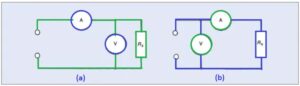
circuit that uses a voltmeter and an ammeter to determine an unknown resistance. In this circuit, only the current passing through the resistor is measured by the ammeter, while the voltmeter measures the voltage drop between the resistor and the ammeter when they are connected in series.
To obtain accurate results, the voltage drop across the circuit resistor must be much higher than the voltage drop across the ammeter. For example, if the ammeter measures 50 A and has an internal resistance of 5 kΩ, the voltage drop across the meter is calculated as V = IR = 50 A x 5 kΩ = 0.25 V. Therefore, the voltage differential (PD) across the resistor should be several times this amount, at least 60 V, to obtain accurate measurements.
However, the accuracy and adaptability of this method are not very good because it requires two meters, and there are more opportunities for error. In addition, the voltages and currents must be adjusted to match the ratings of the resistor and the meter. Therefore, this method is not commonly used.
If an excellent analog multimeter with a high internal impedance is available, the circuit shown in Figure 1(a) is typically used instead. Some analog multimeters have input impedances of at least 10 MΩ, which puts the circuit under less stress and improves accuracy. Alternatively, a good digital multimeter can also be used if it has sufficient precision.
2)-Wheatstone Bridge
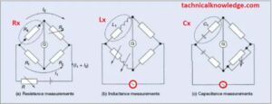
The Wheatstone Bridge is a popular and precise method for measuring medium resistance. It was first described by S.H. Christie in 1833 and later developed by Charles Wheatstone in 1843. The original circuit was designed to measure resistance values accurately, but it has since been modified to work with a wide range of circuits that can measure different values.
In the Wheatstone Bridge circuit shown in Figure 2(a), the fourth leg of the bridge consists of the unknown resistor and three known resistors. Two modifications for measuring capacitance and inductance are shown in Figures 2(b) and 2(c), respectively. These modified circuits are named after the people who made them, but they are all based on the original bridge circuit.
One limitation of the Wheatstone Bridge is that it can be affected by heating and thermoelectric effects, which can cause measurement errors. Additionally, the Wheatstone Bridge is relatively expensive compared to other methods for measuring resistance.
However, the Wheatstone Bridge is highly precise and can measure resistances down to 0.01 with high-quality equipment. The original circuit has been further modified to allow for even greater precision, with some variations able to measure down to 0.001.
The ratios of the resistors R1 and R2 in the bridge’s arms can be adjusted to measure resistances that are much higher or lower. The circuit is set up correctly when the meter reads “0” or when the pointer on the meter stays at “0.” The voltage used to power the bridge does not affect its accuracy.
Overall, the Wheatstone Bridge remains a reliable and widely used method for measuring resistance in a variety of circuits.

When the Wheatstone Bridge is balanced, the voltage across the unknown resistor Rx (in Figure 2(a)) is equal to the voltage drop across resistor R1. This is because the potential across resistors R2 and R3 are also identical to each other. This can be seen in the following example:
Suppose R1 = 100 Ω, R2 = 50 Ω, and R3 = 200 Ω. If a voltage of 5 V is applied across the bridge, the current flowing through the circuit can be calculated using Ohm’s law:
I = V/R total = 5 V / (R1 + R2 + R3) = 5 V / (100 Ω + 50 Ω + 200 Ω) = 0.02 A
The potential difference across R1 can be calculated using Ohm’s law:
V_R1 = IR1 = 0.02 A x 100 Ω = 2 V
Since the bridge is balanced, the voltage across the unknown resistor Rx is also 2 V. This can be measured using a sensitive rotating-coil meter or galvanometer with a center-zero scale.
In summary, the Wheatstone Bridge circuit is a precise method for measuring resistance, and the voltage used to power the circuit does not affect its accuracy. However, the use of high or low voltage can affect the amount of current flowing through the circuit, which can cause overload and damage to the meter in an imbalanced situation. A sensitive rotating-coil meter or galvanometer is typically used to measure the voltage across the unknown resistor when the bridge is balanced.
In real-life Wheatstone Bridge circuits, the resistance legs R1 and R2 are often adjustable in ratios of 0.1, 1, 10, 100, and 1000 to increase the range of the bridge circuit and allow it to handle a wider range of values. However, this also means that when determining resistances using the bridge, factors like multiplication may need to be taken into account.
In some cases, the precise values of R1 and R2 in the Wheatstone Bridge circuit may not be known. In these cases, they are represented as switches, with the distance between them shown by the position of the switch. The value specified by the programmable resistor R3 is directly read by Rx, and the result obtained by applying R3 to the null location is then multiplied or divided by the ratio shown.
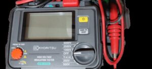
3)-High voltage Insulation Resistance tester
In real-world scenarios, it is neither possible nor convenient to measure very high resistance levels with a circuit like the one in Example 2. To ensure that a sufficient amount of current can flow in the circuit being tested, a high voltage is necessary. This high voltage is needed to obtain accurate readings with a meter. Australian Standards define minimum voltages for testing circuits, which are typical twice the operational voltage of the circuit. For example, the recommended test voltage for a 240 V circuit is 500 V, and 1000 V should be used when testing between phases.
The first instrument designed for tests of this kind was likely produced by an English company now called Meggar Instruments Ltd. The original name of the unit was Ever Shed and Vignola’s, while “Meggar” was its trade name. The term “Meggar” has since become a generic phrase commonly used to refer to all similar test tools, which are known as insulation testers. Different companies produce similar test tools, which should all be called insulation testers.
To generate the voltages needed for insulation testing, there are two main methods: using dry cells and an electrical circuit or using a hand-cranked generator.
4)-Insulation testers powered by generators
For an insulation tester to be truly portable, it must have an internal power source. In the original meter (Megger), a generator was manually turned to generate the necessary power. Earlier models used a DC voltage generator, but later ones used the power of modern magnets spinning inside a coil to create an alternating voltage. The AC voltage was then converted to DC on the inside, which was used to power the instrument.
Figure 3 shows the circuit of a DC generator with an insulation tester. Analysis of the circuit reveals that it is a version of the series ohmmeter circuit. This is because the generator, the deflection coil, the deflection coil resistor, and the resistance being measured are all connected in series.
The moving coil with the attached pointer is actually made up of two coils that are fixed at an angle. A second resistor and the second coil are connected in series across the voltage source that powers the instrument. This second coil functions as a return spring in place of a traditional restraining spring and is used to reset the pointer to zero.
5)-Testing for Continuity
A different type of circuit is used in a megger to test the continuity and resistance of wires in an installation. While the traditional megger functions as a series ohmmeter for resistance ranges of 0-100 M, 0-200 M, or 0-550 M, the continuity tester works as a parallel-connected ohmmeter. The typical resistance range of the continuity tester is determined by its manufacturer.
Earthing continuity checks are commonly conducted using the continuity section of a megger.
6)-Insulation testers that operate on batteries
A bank of dry cells is often used to power an electronic circuit in preventive and corrective measures made by different companies. The output of the circuit is high-voltage, high-frequency AC, which must be rectified before it can be used to power the instrument. Although the entire equipment is often smaller and lighter than a generator-powered instrument, care must be taken to ensure that the tester is functioning properly.
Once an adequate DC voltage is reached, the device works similarly to one powered by a generator. The resistance range for standard operation is 0-200 M. There are standard versions with 100 V, 250 V, 500 V, 1000 V, 2500 V, and 5000 V that have the same accuracy as the Megger.
One of the test probes often has a switch that needs to be held down while the instrument is in use, as the instruments are battery-operated. The battery is unplugged when the probe is released. Modern insulation testers have a built-in switching power source or inverter circuit that can turn 1.5 V batteries into the high voltages they need to work.
Digital readouts are available on more recent battery-operated insulation tester devices, with the power from the batteries being used to power the readout directly. Given the wide range of different types of tests, the technician’s choice of instrument, whether analog or digital, is usually a personal one.
The final position of each coil is determined by the relative quantities of current flowing in each coil. One current is controlled by the voltage source, while the other is controlled by the current flowing through the test circuit. Normal measurement ranges have a fair amount of precision and typically range from 0-200 M.
7)-Care in the Use of Meggers
Using a 500-volt Megger irresponsibly can result in an electric shock. Accidental contact with the test leads can cause unpleasant electric shocks, which can also happen when other technicians are working with the same wires being examined. Higher voltages are often used to test underground wires, with 3000 V output Meggers being commonly used for this purpose. In addition to the direct electric shocks from the instrument, the capacitance effects of the cable can also pose a risk, especially for MIMS cables and subterranean cables that are metal-sheathed or armored.
Capacitance is created by the cable’s construction, which can hold an electric charge between the conductor and the metal sheath that protects the cable. The DC in the Megger creates this charge, which can vary significantly from one cable to the next. Capacitance is usually given in microfarads per unit length. A typical cable has a capacitance of about 0.2 F/300 m, while others may have larger or lower capacitances. This capacitance corresponds to an energy storage of about 9 J at 3000 V, which can deliver a shock strong enough to temporarily incapacitate a technician and require medical attention.
In an airport where there may be several kilometers of underground wire, the risk of electric shock is high. This translates to an energy content at a voltage that can be lethal, even with a relatively short length of buried wire. The cable should be discharged after testing to avoid potential risks. Electricians usually do this by touching a screwdriver or something similar to the sheath or conductor and making a short, but caution should be exercised to avoid additional potential risks. Before relying on a Megger’s capacitance-based installation reading, the operator should ensure that the installation is powered up to the voltage of the Megger.
This is often achieved by testing a single conductor for an extended period. Once the reading stabilizes at one value, the meter often indicates that this has been achieved. For example, the Megger may provide a reading that shows a low-resistance path to earth when testing the resistance of one conductor in an underground cable to its sheath. As the test continues, the Megger reading usually rises to a much higher and more satisfactory level.
8)-Testers for Fault Loop Impedance
The fault loop impedance tester is an important tool for electrical workers to evaluate the parameters of the fault loop in an installation. The fault loop is the path from the main earth of the installation back to the supply point where the primary neutral is grounded. The tester provides an indicator of the path’s impedance by connecting one phase of the installation to a known resistor and measuring both the voltage with no problems and the voltage with simulated problems.
This tester can do the work of both a megger and a continuity tester, as well as test the effectiveness of any devices in the installation that uses residual current. The loop impedance reading in ohms is given after processing in the instrument. Safety devices and devices that use residual current require a good earth return.
However, it is important to note that when testing loop impedance, especially on newer electrical equipment, the device may at least trip and may even be damaged. This can result in a break in supply service, which can be a minor inconvenience at home or a major safety issue in an industrial facility.
A common device for measuring fault loop impedance, which is shown in Figure 6, is known as a fault loop impedance meter. These testers are typically supplied with two types of leads – one with a male plug for testing socket outlets, and the other with crocodile-type clamps for testing electrical apparatus and equipment.
When assessing the fault loop parameters of an installation, it is critical that electrical workers comply with the applicable rules and regulations to ensure self-regulation. By doing so, they can ensure that testing is conducted safely and efficiently, and that the results obtained are accurate and dependable. Adhering to these guidelines enables electrical workers to uphold high standards of quality when carrying out electrical testing.
Leave a Reply