
1-What is a high voltage transformer?
A high voltage transformer is a type of transformer that operates at high voltage levels. This transformer is specifically designed for high-voltage testing laboratories for high voltage testing purposes. During regular operation, it must withstand lighting impulse surges and transient voltages that occur when the equipment ( cable, insulation, breakers, etc.) under test breaks down. Therefore, the transformer’s insulation must be carefully designed to withstand such an impulse voltage. Typically, high-voltage transformers are single-phase core-type transformers.
These transformers are usually immersed in oil, and Bakelite or Press Board sheets and paper are used to separate the low-voltage (415 volts) winding from the high-voltage.
KV up to 500 KV) winding. High-voltage transformers used for testing high-voltage cables must supply sufficient electric current, which can result in a significant amount of heat generation. Thus, the cooling system of these transformers must be meticulously designed. It is crucial to ensure proper transformer voltage regulation and take special care.
In insulation testing , the required current is relatively low. However, when the insulator breaks down occur during testing, a high amount of current flows through the transformer. To limit this current, a high resistance is connected in series with the transformer or a commonly used overcurrent relay for protection . Since insulation testing does not require high currents, high-voltage transformers used for this purpose do not need a high kVA rating.
The testing purposes of the transformer vary based on its ratings. For voltages up to 500 kV, typically, only a single unit of the high-voltage transformer is used.
Concerning transformers with ratings exceeding 500kv, a single transformer is not an economical option due to its large size. In such scenarios where voltage requirements are more than 500 kV, two transformers are connected in series to achieve the necessary voltage output.
The diagram below illustrates the typical cascading connection of two transformers.
2-Working of a high voltage transformer
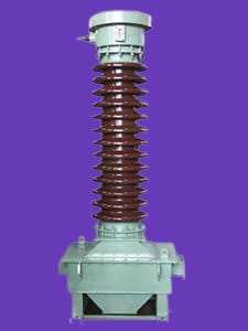
The low voltage (220V single phase & Three Phase 415V, 433V) is fed to the low voltage winding of the step-up transformer , as shown in the figure above. The transformer tank is insulated from the ground.
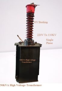
The secondary winding of the transformer is linked to the earthed tank, and the other end is connected via a high-voltage bushing. This bushing is specifically designed to handle full secondary high voltage in relation to the earthed potential of the transformer tank.
Furthermore, a tapping terminal runs through the high-voltage bushing, and the high-voltage end is linked across the primary winding of the second transformer.
The tank of the second transformer is linked to one end of the secondary winding. Unlike the first transformer, the tank of the second transformer is not earthed. Instead, it is earthed for the whole secondary voltage of the transformer. One end of the second transformer’s high voltage or secondary winding is earthed, while the other end comes out through the high voltage bushing to feed high voltage to insulation and the equipment under testing.
The induction regulator method is highly suitable for high-voltage transformers used for power cable testing purposes. Its gradual voltage variation at any load magnitude makes it advantageous for such work.
3-Voltage Regulation High voltage Transformer
On the high voltage side of a transformer, it is advised to avoid any surges. Moreover, to ensure precise voltage readings, the voltage regulation of the transformer must be steady and smooth.
Furthermore, sudden fluctuations in voltage should be avoided during the testing process, and the voltage waveform should remain a sinusoidal waveform when the input voltage regulator is used.
By modifying the input voltage on the primary side, the output voltage of a high voltage transformer can be adjusted as required.
To achieve this, the input voltage can be varied through the following means:
- Alternator field current varies.
- adding inductance or resistance to the supply circuit coming from the alternator.
- using an induction regulator.
- using a tapped transformer.
4-High voltage transformer design parameters
The terms “high voltage transformer design parameters” refer to the various elements and requirements considered when designing and building high voltage transformers.
The transformer’s maximum voltage rating, power rating, winding configuration, core material, and insulation class are some crucial design factors. The transformer’s maximum voltage rating determines the voltage ranges at which it can operate without harm. The power rating specifies the maximum power the transformer can handle without breaking.
The winding configuration, or how the primary and secondary windings are arranged in the transformer, affects the transformer’s efficiency, capacity to carry current, and ability to regulate voltage. The material used for the core influences the transformer’s efficiency and magnetic characteristics. A transformer’s ability to withstand high voltages and avoid electrical breakdown also depends on its insulation class.
The frequency of operation, the cooling system, the transformer’s physical dimensions, and its weight are additional design factors that might be considered. High-voltage transformers can be designed to meet the unique requirements of various applications by carefully choosing and optimizing these design parameters.
5. Importance in Electrical Systems
The significance of high voltage transformers lies in their ability to step up or step down voltage levels, making it possible to transmit electricity across various voltage grids. Without these transformers, the efficient distribution of power would be a formidable challenge.
6.Key Components of High Voltage Transformers
High voltage transformers, integral to the efficient functioning of electrical systems, consist of several key components that work in harmony to ensure the smooth transmission and distribution of power.
6.1. Transformer Core:
The core serves as the foundation, typically constructed from laminated iron or steel. Its role is to provide a low-reluctance path for the magnetic flux generated during the transformation process.
6.2. Windings:
Windings, comprising primary and secondary coils, encircle the transformer core. These coils facilitate the transfer of energy through electromagnetic induction, a fundamental process in voltage transformation.
6.3. Insulation:
Insulation acts as a protective layer, preventing unintended electrical contact between the windings. This crucial component ensures the safety and reliability of the transformer during operation.
6.4. Tank:
The transformer is enclosed in a tank, often filled with oil, which serves as a cooling medium. The tank provides protection from external elements and houses other components like bushings and tap changers.
6.5. Bushings:
Bushings are insulating devices that allow electrical conductors to pass through the transformer tank. They play a crucial role in maintaining the integrity of the insulation and preventing leakage.
6.6. Tap Changers:
Tap changers enable the adjustment of the transformer’s turns ratio, allowing for voltage regulation. This feature is vital to adapt to varying load conditions and ensure a stable power supply.
6.7. Cooling System:
Transformers generate heat during operation. Efficient cooling systems, employing methods like oil or air cooling, are implemented to maintain optimal operating temperatures and prevent overheating.
6.8. Buchholz Relay:
This protective device is installed in oil-filled transformers to detect and respond to internal faults such as overheating and gas accumulation, ensuring early intervention to prevent major failures.
6.9. Conservator Tank:
The conservator tank accommodates oil expansion and contraction due to temperature variations, preventing excessive pressure build-up and ensuring the transformer’s long-term reliability.
7. Working Principle
7.1. Voltage Transformation Process
The magic of a high voltage transformer unfolds in its ability to transform electrical energy. By inducing a magnetic field through the primary winding, the transformer can step up or step down voltage, depending on the configuration and turns ratio.
7.2. Core and Windings
The core, typically made of laminated iron or steel, provides a low-reluctance path for the magnetic flux. Surrounding this core, the windings—comprising primary and secondary coils—facilitate the transfer of energy through electromagnetic induction.
7.3. Role of Insulation
Insulation acts as a protective barrier, preventing unwanted electrical contact between windings and ensuring the transformer’s safe and reliable operation. Commonly, materials like oil or specialized polymers are used to insulate these crucial components.
8. Types of High Voltage Transformers
8.1. Power Transformers
Power transformers, often seen in power stations, are designed for high-voltage transmission. They play a key role in stepping up voltage for efficient long-distance power transmission.
8.2. Distribution Transformers
On the other hand, distribution transformers are responsible for stepping down voltage for local distribution. They are commonly found on utility poles and in substations, ensuring electricity reaches our homes and businesses.
8.3. Instrument Transformers
Instrument transformers, like potential and current transformers, are crucial for providing accurate measurements of voltage and current in electrical systems. They find application in both power generation and distribution.
8.4 HVDC Transformers
HVDC transformers are crucial for converting AC power to DC power in high-voltage direct current systems, which are essential for long-distance power transmission and interconnecting different power grids.
These transformers can be configured in various ways, including single-phase, three-phase, or twelve-phase setups. They also have different winding connections, such as star-star, star-delta, or delta-delta, chosen based on the HVDC system’s type and topology. Unlike conventional AC transformers, HVDC transformers must endure high DC voltages and currents, manage harmonics and polarity reversals, and withstand transient overvoltages. They also require superior insulation and effective cooling to operate reliably.
9. Applications
9.1. Power Transmission
High voltage transformers are the backbone of power transmission systems, allowing electricity generated at power plants to travel vast distances before reaching end-users.
9.2. Industrial Use
In industrial settings, these transformers power heavy machinery, contributing to the manufacturing processes across various sectors.
9.3. Renewable Energy Systems
With the rise of renewable energy sources, high voltage transformers play a vital role in integrating solar and wind power into the existing electrical grid.
10 Design Considerations
10.1.Material Selection for High Voltage Transformers
Choosing the right materials is crucial for the performance and longevity of high voltage transformers:
Transformer Core: Laminated iron or steel for high magnetic permeability and reduced losses.
High-voltage Windings: Copper for high efficiency, or aluminum for weight considerations.
Insulation: Oil-impregnated paper, polymer films, and pressboard for dielectric strength and thermal stability.
Tank: Steel with corrosion-resistant coatings for durability and leak prevention.
Oil: Mineral oil with high dielectric strength and cooling properties.
Bushings: Porcelain or composite materials for electrical insulation and mechanical strength.
Tap Changers: Copper and alloys for electrical conductivity and resistance to wear.
Cooling System: Aluminum or copper for efficient heat dissipation.
Buchholz Relay: Components resistant to oil and corrosion for reliable fault detection.
Conservator Tank: Steel with corrosion-resistant coatings to withstand oil expansion.
11-Cooling Systems
As transformers generate heat during operation, effective cooling systems, often employing oil or air, are implemented to maintain optimal operating temperatures.
12. Safety Features
Incorporating safety features such as overload protection and insulation monitoring ensures the longevity of the transformer and minimizes the risk of electrical failures.
13. Maintenance and Troubleshooting
13.1. Regular Inspections
Routine inspections are essential to identify potential issues early on, preventing costly downtime and ensuring the continued reliability of the transformer.
13.2. Common Issues
From overheating to insulation breakdowns, transformers may encounter various issues. Being aware of these common problems aids in prompt troubleshooting and maintenance.
13.3. Safety Measures
Maintaining a safe working environment around high voltage transformers involves following safety protocols, utilizing personal protective equipment, and implementing emergency response plans.
14. Future Trends
14.1. Smart Transformer Technology
The future of high voltage transformers lies in smart technology, where transformers are equipped with sensors and communication capabilities for real-time monitoring and control.
14.2. Integration with Smart Grids
As smart grids become prevalent, high voltage transformers will seamlessly integrate into these advanced systems, enhancing grid efficiency and reliability.
14.3. Sustainable Practices
With a growing emphasis on sustainability, the development of eco-friendly transformer technologies aims to minimize environmental impact while maintaining optimal performance.
15. Advantages of High Voltage Transformers
15.1. Efficient Power Transmission
High voltage transformers enable efficient power transmission, minimizing energy losses during long-distance transportation.
15.2. Economic Benefits
The economic benefits of these transformers are evident in their contribution to cost-effective power generation, distribution, and utilization.
15.3. Environmental Impact
Efficiency in power transmission directly correlates with a reduced environmental footprint, aligning with global efforts toward cleaner and greener energy solutions.
16. Challenges and Risks
16.1. Overheating and Overloading
One of the primary challenges involves managing heat generated during operation and preventing overload conditions that could compromise the transformer’s integrity.
16.2 Environmental Concerns
While transformers contribute to efficient power systems, the disposal of outdated transformers poses environmental challenges due to the presence of oil and other materials.
16.3. Safety Regulations
Adhering to strict safety regulations is paramount to ensure the protection of both human life and the environment, making compliance a constant consideration in transformer design and operation.
17. Conclusion
In conclusion, high voltage transformers are the unsung heroes shaping our modern electrical landscape. From their intricate design to their pivotal role in power transmission and distribution, these transformers play a
Leave a Reply