
Load loss Test or short circuit test in Transformer
Introduction of Transformer load loss
Because of the low power factor and frequently high test currents, measuring load loss on a power transformer needs special attention and precise measuring equipment.
At the rated frequency, the load loss for a pair of windings is measured with voltage applied to one winding’s terminals, the other winding’s terminals short-circuited, and it’s conceivable that additional windings are open-circuited as well.
The supplied current must equal the corresponding rated current. The measurements must be performed immediately to prevent major mistakes from temperature increases.
The square of the ratio of the test current to the rated current must be multiplied by the measured value of load loss.
The figure that results must then be adjusted to reference temperature. Conventionally, it is assumed that all other losses increase inversely with temperature and that ohmic losses vary directly with temperature.
The 3 different two winding combinations on a three-winding transformer are measured. Recalculating the data, losses are assigned to specific windings. Accordingly, total losses for defined loading scenarios involving all of these windings are calculated.
Errors and losses in external circuits should be kept to a minimum. If they are not obviously negligible, correction for measuring transformer errors and for test connection resistance should be performed.
What is the purpose of short circuit test or load loss test?
The transformer short circuit test is used to measure short circuit parameters, including copper losses, equivalent resistance, voltage regulation, and percentage impedance under full load. It is recommended that this test be performed under rated current conditions.
Why are short circuit tests or load loss test performed?
- To calculate the transformer equivalent resistance and reactance.
- To measure the copper loss (varying losses) in the transformer.
- By obtaining the results of the short circuit test, it is possible to assess the transformer’s voltage regulation or percentage impedance z%.
How to Perform a Short Circuit or load loss test Test
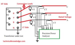
On the high voltage side, a short circuit test is performed at the rated current with the L.V. side closed-circuited with a copper bus bar. It is done on the H.V. side because rated current may happen there more conveniently as compared to the L.V. side.
Operational Steps of Short Circuit Test or load loss test
- First of all note down the ambient temperature of your under-test transformer and the temperature should be between 10 to 40 degrees Celsius, according to specification IEC-60076-1.
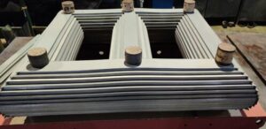
- short the Low voltage/ secondary/ Side of the under-test Transformer.
- Apply Voltage on the High voltage side/ primary side at the rated current. calculate rated current from this formula Current = Power /Voltage x 1.732
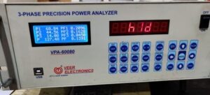
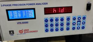
- Note the Power and Voltage from your power Analyzer and convert the losses on 75 C using this formula MF= (235+75)/(235+Ambint temperature)
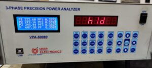
- This power will be equal to your Load losses or copper losses and Voltage will be equal to the impedance voltage at the ambient temperature.
3 in 1 || Load loss Test, short circuit test in Transformer and load losses calculation
Introduction of the no-load loss
The operational efficiency of a transformer is intimately connected to its no-load losses. These losses keep occurring as long as the transformer is in operation. For an operational economy, it is crucial that there are no load losses. The heating test also takes into consideration no-load losses. When measuring the no-load loss and current of a transformer, one of the windings (usually the HV winding) is left open while the other is given the rated voltage and frequency (50 HZ or 60 HZ) that is being measured.
The no-load current (Io) and no-load losses (Po) are measured during this test. The frequency and waveform of the applied voltage have a major impact on the observed losses. Because of this, the voltage waveform should be perfectly sinusoidal and at its rating.
Most of the time, the tests are done with the supply voltage going from 90% to 115% of the transformer’s rated voltage in small steps. This lets the values at the rated voltage be found as well.
How to produce no load losses in Transformer core.
A power transformer’s core will always use energy when it is energized, and this energy will be in the form of heat. This is called “no-lead losses.” Irrespective of whether the transformer is carrying a load or not, these losses will always happen. No-load loss has various components and is dependent on the quality of core manufacturing and the CRGO steel sheet used in the core building.
Interlaminar loss, hysteresis loss, eddy current loss, and extra losses. A quick peek at these components:
Hysteresis Loss.
The size of the hysteresis loop and frequency are both related to hysteresis loss (a characteristic of the power transformer core material and the peak flux density of 1.5 tesla or 1.7 tesla). Hysteresis loss is the term for the heat that is released as the atoms of the core material realign themselves to line up with the magnetic field being applied.
Eddy current loss
Eddy current (EC) loss can be considered to be divided into two parts: the classical EC loss, which is dependent on the thickness of the core and resistance of lamination steel (core), and the non-classical EC (anomalous) loss, which depends on the grain size of the core material (a larger grain size will result in more loss) and magnetic domain movement during the magnetizing cycle. Eddy current loss is proportional to the square of the supply frequency and the square of the maximum flux density. The second causes higher losses than the first and may be greatly minimized by particular processing of the core material.
Measurement of no load losses.
The frequency should be within plus or minus 0.5% of the rated frequency as measurements will be performed using a power analyzer. Before beginning the test, it might be required to overexcite the system by gradually raising the voltage to 110%,
- Holding it there for a short period of time,
- Then gradually lowering it to a minimum.
- The observed loss will need to be adjusted since the voltage waveform during this test could be affected (these voltage distortions don’t happen while the transformer is performing because the supply system’s impedance is significantly lower than its primary inductance impedance).
- Both the voltmeter reading (U’) and the power analyzer reading (U) of the test voltage must be read throughout the test, and the difference between them should be less than 3% (IEC) or less than 5%. (IEEE).
Precautions
- The testing area should be cordoned off.
- Flashing warning lights should start when a transformer is under testing.
- Use insulation gloves when handling the cables.
- Make sure that the testing person should be at his defined place.
Good day,
I contacted you some days back seeking your cooperation in a matter regarding funds worth $24 Million, I urge you to get back to me immediately through markden1@markkden.com
I await your response.
Thanks,
Mark Den